1 (513) 921-9400
Braking Resistor Theory
When an AC motor is slowed or stopped using an AC variable speed drive, energy is created and regenerated back into the drive system due to the motor producing power like an electric generator. Drive system issues will occur when an application requires a deceleration rate faster than what can be managed by the drive or when the motor speed exceeds the value set by the output frequency of the drive (this later scenario is called an overhauling load condition) which produces more energy than the drive can withstand. This energy needs to be regenerated back into the power system or dissipated as heat using a braking resistor to prevent the drive from shutting down due to an over-voltage trip. A properly designed braking resistor will provide an economical and dependable solution for these issues and greatly improve the braking torque potential of a variable speed drive system resulting in more controlled and faster deceleration times.

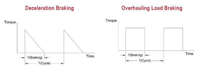
Deceleration Braking vs. Overhauling Load Braking
An overhauling load condition exists when a motor is coupled to a load requiring a deceleration speed which is greater than the power rating of the drive. This condition causes the motor to act as a generator and returns energy back to the drive. The condition is different than a deceleration braking because energy is constant during this period. This means the resistor has to absorb twice the power during the overdrive situation than during a deceleration braking condition. The below graphs detail the basic difference between the two braking conditions:
Calculating the Duty Cycle
Calculating duty cycle is important because it determines the power rating of the braking resistor. In relation to the braking resistor power dissipation and the above graphs, calculating the duty cycle for deceleration braking and overhauling load braking is different because the resistor has to absorb approximately 1/2 the power during a deceleration stop than an overhauling load braking cycle. Percent duty cycle calculations are as follows:
Deceleration Braking: Braking Time / Cycle Time x 100% x 0.5
Overhauling Load Braking: Braking Time / Cycle Time x 100%
How to Specify a Braking Resistor
Crohm Resistors offers a full line of braking resistors that are drive specific to all the major manufacturers of variable frequency drives, however, you can also request a custom design to meet your specific requirements in several ways:
- Ohms and Watts
- Drive HP, Drive Voltage, Duty Cycle and Braking Torque
Caution: Always check to make sure that the ohm value of your braking resistor exceeds the minimum ohm value published for your drive or braking module. Installing a braking resistor with too low an ohm value will cause harm to your drive or braking module. Please call the factory if you need assistance.
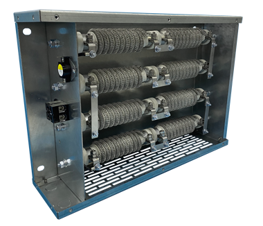
Standard Construction
Standard units normally feature either Crohm Series CW Wirewound or Series CE edgewound resistors installed in an indoor screened enclosure with a galvanized finish and connected together with all stainless steel bus bars. The resistors are wired to a terminal block located in either a separate compartment from the resistors or near the bottom of larger size free standing enclosures. The resistors are wired using only high temperature silicone or teflon coated wire and high temperature lugs. Our standard outdoor braking resistors feature a louvered enclosure with special ventilation components added to the top of the enclosure to insure proper cooling. All of Crohm’s outdoor units feature all stainless steel external hardware.
Accessories and Options
- Protective enclosures for both indoor and outdoor applications
- Custom engineered assemblies with factory interconnections and terminations
- Thermal overload protection
- All Stainless Steel Construction
Click here for a PDF version of this product sheet.