1 (513) 921-9400
Crohm Neutral Grounding Resistors
Neutral Grounding Resistor Theory
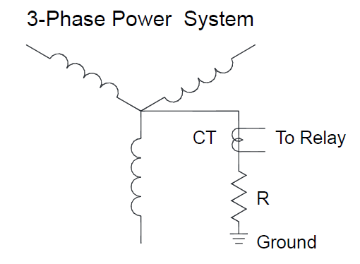
Neutral-Grounding Resistors are used to ground power systems by connecting a resistor between the power system neutral and ground. This lowers the prospective ground-fault current to a predetermined value. A properly designed neutral grounding resistor provides benefits over both ungrounded and solidly grounded systems. By adding a grounded resistor to the system, transient over-voltages do not occur and neutral ground fault current can still flow, allowing it to be detecpoweted and measured. Also, because a resistor is used to ground the system, the very large and destructive ground-fault currents of solidly grounded systems are limited and controlled.
Neutral Grounding Resistor Design
Crohm designs and manufactures neutral grounding resistors per the latest IEEE-32 standards. The key design parameters to consider from IEEE-32 are the allowable temperature rises of the resistor element for different ON times and the applied potential and/or dielectric tests, plus the resistance tolerance tests that insure the final product meets the customer’s requirements.
Time and Temperature Ratings
Time Rating IEEE Standard 32 specifies standing time ratings for Neutral Grounding Resistors with permissible temperature rises above 30˚C ambient as shown in Table 3. Time ratings indicate the time the grounding resistor can operate under fault conditions without exceeding the temperature rises.
- 10-Second Time Rating: This rating is applied on neutral grounding resistors that are used with a protective relay to prevent damage to both the neutral grounding resistor and the protected equipment. The relay must clear the fault within 10 seconds and not exceed a 760C temperature rise.
- 60-Second Time Rating: This rating is often used to limit ground current on multiple outgoing feeders. This reduces equipment damage, limits voltage rise and improves voltage regulation. Since simultaneous grounds could occur in rapid succession on different feeders, a 10-second rating is not satisfactory. The 60-second rating is applied with a maximum operating temperature not to exceed 760C.
- 10-Minute Time Rating: This rating is used infrequently but is applied in unique process applications requiring extended fault times. The 60-second rating is applied with a maximum operating temperature not to exceed 610 C.
- Extended-Time Rating: This is applied where a ground fault is permitted to persist for longer than 10 minutes, and where the NGR will not operate at its temperature rise for more than an average of 90 days per year. The Extended-Time rating is applied with a maximum operating temperature not to exceed 610 C.
- Continuous Time Rating: This rating applies where the neutral grounding resistor is expected to be operating under ground fault conditions for more than an average of 90 days per year and/ or it is desirable to keep the temperature rise below 385˚C.
Neutral Grounding Specification and Scope
Crohm offers a complete line of neutral grounding resistors that are designed to meet your specific requirements. To order a neutral grounding resistor you must have the following information:
- System Voltage or Line-to-Neutral Voltage
- Fault Current
- Time Rating
- Enclosure Type – Open, Indoor or Outdoor
- Options or Special Requirements (Current Transformer, Elevating Stand, Special Paint or Finishes, Seismic Zone Areas, Disconnect Switch)
Conformance to National Standards
The neutral grounding resistors shall be designed and factory-tested to IEEE Standard 32. The neutral grounding resistors shall be designed to conform to Seismic, Zone 2 requirements of the Uniform Building Code unless otherwise specified.
Service Conditions
Neutral grounding resistors shall be suitable for outdoor service and will be mounted on permanent structures.
Ratings
The neutral grounding resistors shall have the ratings indicated on the previous page (These ratings will be specified by the customer)
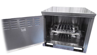
Design Details
The neutral grounding resistor shall be provided with an outdoor safety enclosure with a hinged front door and a pad lockable handle. The enclosure will have a solid top, screened bottom, side covers, and fork lift channels for handling ease. The enclosure finish will be mill galvanized or ANSI 61 grey unless as specified. The resistor will consist of stainless steel edgewound resistor mounted on spool insulators and double insulated for mounting frames. The resistor terminals must be stainless steel. All resistor end frames, hardware, and non-current carrying spacers will be galvanized steel. If more than one resistor frame is required, series connections shall be stainless steel. The resistor bank or banks will be mounted on porcelain standoff insulators with a rating equal to or greater than the line to neutral voltage. Neutral grounding resistors must be delivered to the jobsite completely assembled and ready for installation.
Nameplates
Neutral grounding resistors shall be provided with a nameplate which shall be fixed to the exterior of the enclosure and on the inside of the front door.
Drawings
The supplier shall submit approval drawings within 5 working days after notification of contract award.
Test Reports
Supplier shall submit certified test reports in accordance with IEEE Standard 32.
Manuals
Supplier shall submit complete Instruction and Maintenance manuals at the time of shipment. The manuals shall give complete and detailed instructions for unpacking, installation, inspection, connection, and maintenance
Click here for a PDF version of this product sheet.